Phase Locked Loop (PLL) Basics II

There are several filters one can use for the feedback loop. The simplest is the passive low-pass RC filter. I used the active integrator, which use a R and C element. To ensure a DC bias does not work itself into the capacitor, I put a discharge resistor in parallel with C. The active filter has more gain than the passive filter. The phase shift in the beginning is -90. I don't know if this helps keep our signals at -90 or not. I scoped both the passive and active filter action by monitoring the relationship of the inverter voltage and current, and I can say that the latter maintained a tighter lock on a -90 phase difference during changes in the tank's resonant frequency. Below is a table of some filters. I used one similar to the second. I add a variable voltge input to V- on the op-amp, which allows me to fine tune the frequency. I usually tune it slightly above resonance, using a voltage monitor on the tank voltage for the near-high point. One other thing: you need a gain of -1 after the active filter because it inverts the signal. The -1 gain op-amp will restore the proper polarity.

Let's talk about how we set the free-running PLL frequency and the range it can capture. If the resonant frequency falls with the PLL capture range, the PLL will be able to find the frequency that maintains the 90 degree shift that we want, and maintain this phase lock as the frequency required for this phase difference changes over a wider range of frequencies.
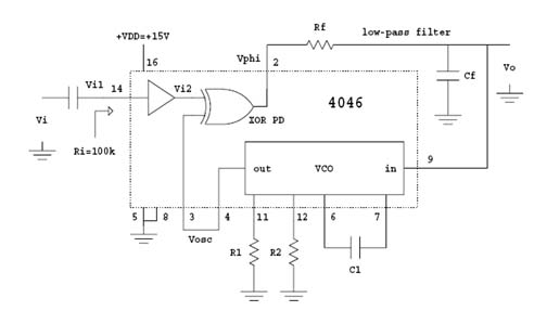
Here is the chip


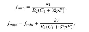
These forumulas can be off and require constants as shown below:

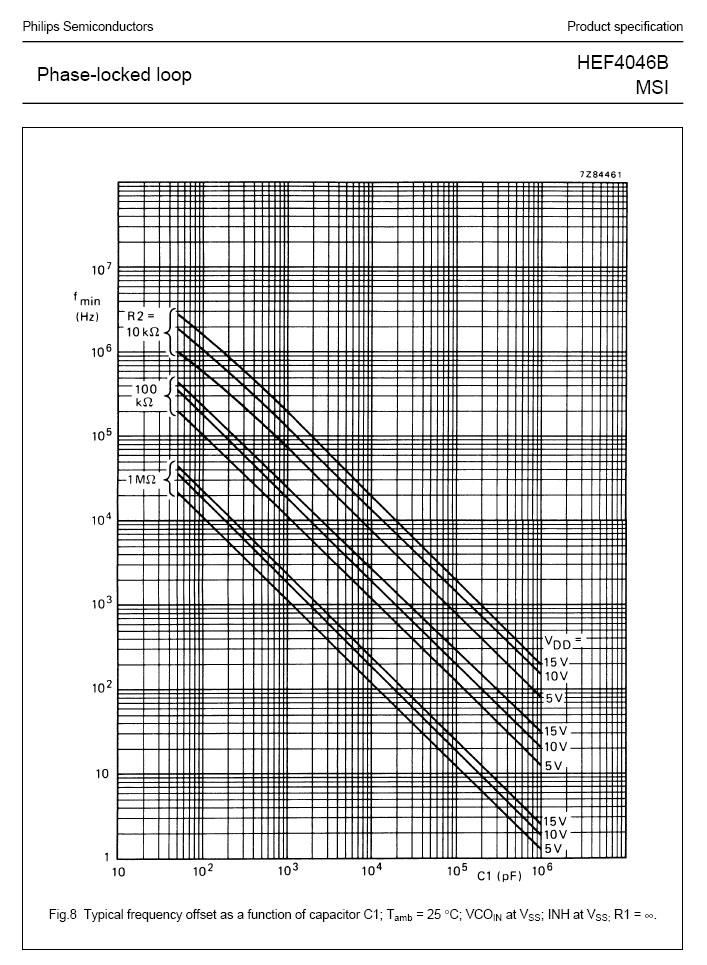
You can also use graphs on the manufacturer datasheets to get you in the ballpark for the values you need. The first step is to determine the capacitor value that will get you near your Fres at a given Vdd voltage. Determine the R value you need for Fmin, and then determine the R you need for Fmax.

Let's do a quick example. My Fres is 65kHz and my supply is 15v. Actually, my supply is 14.4v, because I have a diode to protect from hooking up the pos and neg in reverse. I go up the left hand side to the 60khz row and across to the 15v supply line. I go straigtht down and get a C1 of 300pf. This will be my starting point for my equations. Using C1 = 330pf, I will pick some R values and measure the actual frequency in order to determine the values of the constants K1 and K2.
We want to have the center frequency, (Fmin + Fmax)/2, equal our resonant frequency, and we want about 10-15kHz on either side. Now, the chips can vary from the equation by a factor of 4, so you need to multiply each equation by a constant. Take a 100k resistor for R2 and R1. Ground pin 9 and measure Fmin. Next, connect pin 9 to Vdd and measure Fmax. This will give you K1 and K2. I measured 50kHz for Fmin, giving me a K1 of 1.81. I then connected pin 9 to Vdd and got 154khz. Subtracing Fmin, 50khz, I was able to dedue that K2 equals 3.78. My frequency is 65kHz, so I want something between 50-80kHz. I will use a 330pf capacitor, as determined from the graph, and values of K1 = 1.81 and K2 = 3.78. I now use these values to determine the true values of R1 and R2 that I need, which is 100k and 348k. The calculations are below. Of course, you need to verify this with your scope.
Fmin = 50khz = 1.81/(100,000 x 362e-12)
Fmax = 80khz = 50khz + 3.78/(348,000 x 362e-12)
On my circuit I add a trim pot and another resistor in parallel to R2 with an optional jumper. This gives me a selection of resonant frequency ranges.
So, how does our circuit come together? Let's see.