Tinned Copper Braided Shielding, EMI, Celem Capacitor
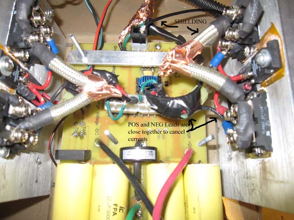
One not only needs to worry about how the emi affects the gate drive on the inverter, but how it affects the PLL feedback loop on the driver. The solution begins by separating the drive circuitry from the high powered inverter section. I now have two boards. One board tracks and generates the drive signal. All of the critical signals are shielded with a grounding plane. The signal exits in a shielded wire that is connected to ground. This goes to the second board. On this board the gate drive lead is shielded with the shield connected to ground. The mosfet modules are electrically isolated from the heat sink. If they are connected the heat sink will broadcast the inverter waveform and interfere with the feedback signals. The gate drive signal goes through a damping resistor. I originally had a ferrite bead, but found this was not necessary. I have copper shielding completely covering the gate drive lead. Inside the shielding I have the lead going to a 10 ohm resistor. It is important that each switch has its own resistor as close to the gate as possible to reduce oscillations. So far this has worked out well. I have seen what happens with poor shielding, and it isn't pretty.
Below is a picture of the inverter with the shielded leads.

I also had to modify the feedback control loops. I use RC networks to filter the pulse-waves from the PLL to create a DC feedback signal. I then use RC networks to take the PWM output and convert it into a steady DC signal for the PLL's VCO input. The better my filtering for a smooth signal, the longer the delay. If the delay is too long the system oscillates. If the filtering is not sufficient, the drive signal is course. The trick was to find the right balance.
The tank capacitor was another issue. A rough calculation showed that I was already maxing out the capability of my capacitor bank. I had 20 capacitors that were each rated for a maximum of 14A. I must have had between 200-300A going through them with my 2kw unit. I switched to a water-cooled Celem capacitor that was rated for 600V/1000A (part# CSP-505-2.6uf). The connections were made so that every contact point shared current equally. If you make the connections incorrectly, all the current will go through the closest point and rapidly overheat the copper. I witnessed this and it was not pretty.
I will start elaborating on the modified drive circuit and the inverter on the following pages (to come shortly).
Here is the 10kw unit in action
Here are some links to the levitation coil in action for the 2kw unit
Levitating and melting aluminum
Levitating and melting copper scrap